


Arduino Project: LCD Shield Kit

Jeremy Morgan 
Nov 14, 2015 - 5 min read
Last Update: Mar 8, 2023

AI changed software development. This is how the pros use it.
Written for working developers, Coding with AI goes beyond hype to show how AI fits into real production workflows. Learn how to integrate AI into Python projects, avoid hallucinations, refactor safely, generate tests and docs, and reclaim hours of development time—using techniques tested in real-world projects.
I recently picked up an Arduino LCD shield kit from Adafruit. I’ve wanted to play around with some LCD screens and since this was a self contained kit for $20, I thought I’d try it out. Here’s my thoughts on it.
For this article I’m using an Arduino Mega 2560, obtained from Newark Element 14
The Arduino LCD Shield Kit
The kit comes with the following items:
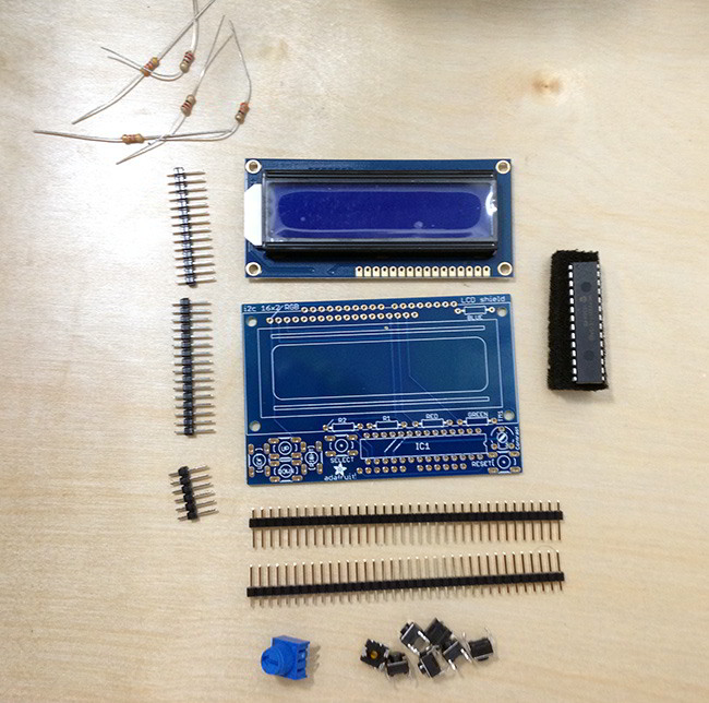
In the kit we have:
- 5 Resistors
- Potentiometer
- Printed Circuit Board
- Header Pins
- Pushbuttons
- i2c Port Expander Chip
It’s definitely a “turnkey” kit that comes with everything you need. The full assembly instructions show you how to build it, step by step.
Bust Out Your Soldering Iron!
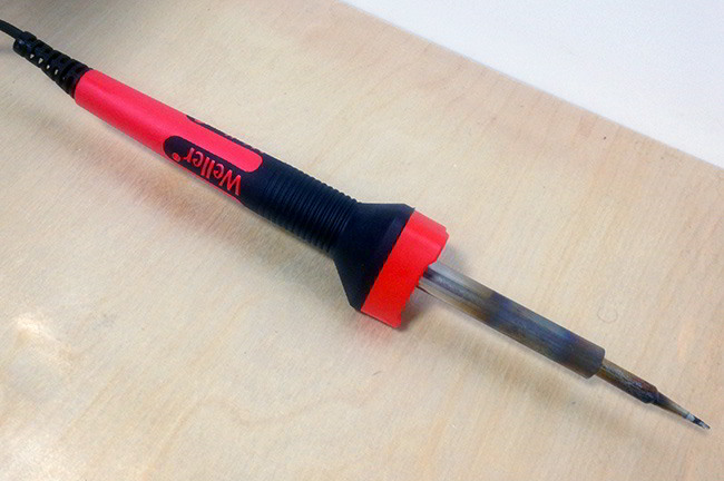
For this kit you will need to do a considerable amount of soldering. Some folks aren’t a fan of this idea, but I love it. This is great for beginners so they can learn soldering techniques and get better at it. Even though this is a complete kit that could be easily shipped soldered and assembled, I think that would be cheating beginners out of the experience of assembly. Not to mention it frees you up to use only the parts you need, or even use them in something else.
You’re a hacker now, embrace it!
Assembling the Shield
For the first step you’ll want to solder on the resistors out of the kit in the following configuration:

An easy way to do this is pull the resistors down through the holes and cross the wires like so. Then once they are all through, solder each piece and trim off the ends.
 Next, add the buttons. You’ll have to be careful with these pins as they are very close together.

Now, install the IC with the notch matching, as shown in the diagram:

Then break apart the header pins and insert them as shown:

You can now place the board on the Arduino so the pins match up.

Now you can solder the pins in. This gives you an interface to your Arduino, but mostly it’s just to keep the sheild stable. At this point you could add risers to the header pins for stacking other devices if you want.
Finally, you then solder on the LCD screen:

And you’re done!

Next we’ll cover how to put some text on the screen.
Displaying Text
The easiest way to interact with this shield is to use Adafruit’s RGB LCD Shield Library. Download that and install it into sketch. (How to install additional Arduino libraries)
To output the message shown above, create a file with the following code:
#include <Wire.h>
#include <Adafruit_MCP23017.h>
#include <Adafruit_RGBLCDShield.h>

Adafruit_RGBLCDShield lcd = Adafruit_RGBLCDShield();

void setup() {
  // Debugging output
  Serial.begin(9600);
  // set up the LCD's number of columns and rows:
  lcd.begin(16, 2);
  // print in first row
  lcd.print("Be sure to drink");
  // set cursor to second row (row 1)
  lcd.setCursor(0, 1);
  // print in second row
  lcd.print("your Ovaltine");
  // set backlight to white
  lcd.setBacklight(0x7);
}

void loop() {
  // do nothing for now
}
Pretty easy right? I hope the comments explain what’s going on. But we have some other buttons on there we want to work with.
We’ll put the following in the loop:
uint8_t buttons = lcd.readButtons();

  if (buttons) {

    lcd.clear();
    lcd.setCursor(0,0);

    if (buttons & BUTTON_UP) {
      lcd.print("pressed UP");
    }
    if (buttons & BUTTON_DOWN) {
      lcd.print("pressed DOWN");
    }
    if (buttons & BUTTON_LEFT) {
     lcd.print("pressed LEFT");
    }
    if (buttons & BUTTON_RIGHT) {
      lcd.print("pressed RIGHT");
    }
    if (buttons & BUTTON_SELECT) {
      lcd.print("pressed SELECT");
    }
  }
This code should be really straightforward. You can check to see if a button is pressed in the loop, and create code based on it. So let’s do something with that.
Turn an LED On and Off with Indicator
Here’s something to try, hook up an LED to a digital pin. I am using the Arduino Mega, and just put it in the board like this:

Now, create a file with the following code:
#include <Wire.h>
#include <Adafruit_MCP23017.h>
#include <Adafruit_RGBLCDShield.h>

Adafruit_RGBLCDShield lcd = Adafruit_RGBLCDShield();

void setup() {
  Serial.begin(9600);
  lcd.begin(16, 2);
  lcd.print("LED MODE:");
  lcd.setCursor(0,1);
  // off by default
  lcd.print("OFF");
  lcd.setBacklight(0x7);
  pinMode(53, OUTPUT);
}

void loop() {

  uint8_t buttons = lcd.readButtons();

  lcd.setCursor(0,0);
  lcd.print("LED MODE:");

  if (buttons) {

    lcd.clear();

    if (buttons & BUTTON_UP) {
      // turn led on
      digitalWrite(53, HIGH);
      // display it
      lcd.setCursor(0,1);
      lcd.print("ON");
    }

    if (buttons & BUTTON_DOWN) {
      // turn led off
      digitalWrite(53, LOW);
      // display it
      lcd.setCursor(0,1);
      lcd.print("OFF");
    }
  }
}
This is pretty straightforward stuff, not that we set “pinMode” to 53,OUTPUT. This is how we set up the pin to light up the LED with the digitalWrite function. By setting pin 53 to HIGH it powers it, and setting it to LOW stops it. The LCD screen then prints the status.


The possibilities are endless here!
Summary
Overall I think this product is a fantastic value. I’ve just barely scratched the surface of what can be done here, and it’s only $19.95. It could be a very valuable display for your projects. It’s easy to assemble and works great. So pick up an Arduino (I really like the Mega 2650) and an LCD shield and start tinkering! Contact me with any cool projects you create!

Skip the hype. The newsletter that keeps you in the know.
AI news curated for engineers. The AI New Hotness Newsletter is what you need.
Zero fluff. Just the research, tools, and infra updates that actually affect your production stack.
Stay up to date on AI for developers - Subscribe on LinkedIn